Difference between revisions of "Ubox ALU 100A manual"
| Line 6: | Line 6: | ||
== Features == | == Features == | ||
# Three low side shunts, 0.5 | # Three low side shunts, 0.5 milliohm x 3. | ||
# Phase filters. | # Phase filters. | ||
# 12V 3A for external devices, such as cooling fan, lights, horn, screen, etc. With recoverable fuse. | # 12V 3A for external devices, such as cooling fan, lights, horn, screen, etc. With recoverable fuse. | ||
Revision as of 11:00, 11 July 2023
Ubox ALU 100A an ESC designed for hi current application in a compact size. 'ALU' is mean for aluminum substrate power stage.
Features
- Three low side shunts, 0.5 milliohm x 3.
- Phase filters.
- 12V 3A for external devices, such as cooling fan, lights, horn, screen, etc. With recoverable fuse.
- 5V 1A with recoverable fuse.
- 3.3V 500mA with recoverable fuse, independent from MCU's.
- Built in BMI160.
- Power button with green and red LEDs, copy the VESC status LEDs.
- Ignite/voltage meter support.
- 12V Fan socket.
- Separated 4 pin 12V socket.
Ports and wiring
The button and ignite
Two or more wheel driving configuration
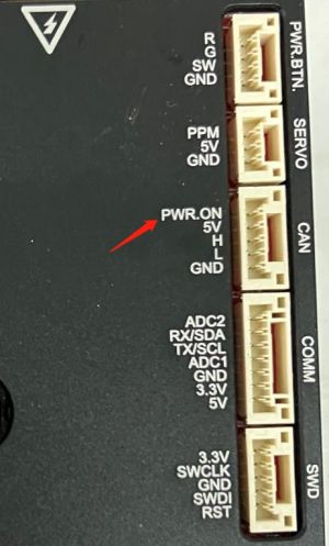
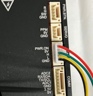
Ubox ALU 100A has a 'PWR.ON' pin in the CAN socket:
This PWR.ON pin can accepts a 5V signal to make power on the Ubox ALU 100A, then the 12V power source of this Ubox will working, consequently the 5V and MCU's 3.3V (3.44V actually) will on. There for we can get all of the 12V power from each Ubox, which is 6A total for two wheel driving, 12A for four wheel driving.
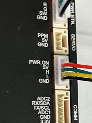
To config a 2WD/4WD, we need to move the 5V wire of the CAN cable to the PWR.ON pin for the slave (follower) Ubox:
The master Ubox side no need to change:
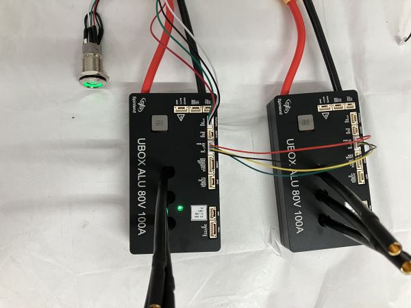
The whole 2WD configuration:
For 4WD configuration, make each followed Ubox's PWR.ON pin receives the 5V signal from its predecessor.
What if I want them running independently? We can pick out the the CAN-H and CAN-L wires from the CAN cable, only keep the GND and 5V wires remain.
Note: Use the 12V from each Ubox independently, don't parallel them directly. Otherwise may damage the Ubox.
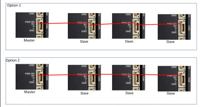
From one of our users drawing, thanks him:
Both option1 and 2 are working, option 1 cable is included in the ESC shipping package.
Concludes and explains
Limits and cautions
- This is an electronic power product. Installation and use requires certain knowledge of electronic circuits and and cautious. The first thing to do before connect to battery or power source is to double check whether the positive and negative wires are correctly connected.
- The Ignite socket is often too high to be safe, Don not plug the power button in it.
- This product is for DIY purpose, so we only offer a very limited warranty.
