How to setup a 4WD with Ubox V1
This is a guide to help our users to setup a 4WD with two Ubox V1(red panel). Ubox V1 was our first VESC product, designed in 2020. our design was not very thoughtful, it is not so convenient for build a 4WD. Thanks to our users, you are very positive about V1.
This guide descripts the configuration of 4WD with two Ubox V1 and Uni1 remote, based on newest FW 5.3 and VESC tool 3.01 PC edition.
Conception
To combine 2 Uboxes to build a 4WD, we need to set one of them as master, the other as slave. The master Ubox receives the remote’s control signal, relay the signal to all the other ESCs through CAN bus.
For Ubox V1, there are two places to pay attention to:
The power on/off control
Ubox V1's power on is maintained by it's built-in 2.4GHz receiver, it's a MCU and 2.4GHz transceiver combo chip. It is only checks the power button to make its own power on/off decision. So we need to give button state to both two Uboxes.
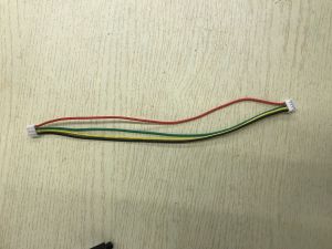
We can parallel connection of two wires, the GND and switch of the button cable, into one button, to make one button to power on/off two Uboxes workable. Like in this picture:

Uni1 remote
If you coupled with Uni1 remote, the receiver inside Ubox will report back data to remote, and the master and slave Ubox share the same radio link channel, the slave Ubox's back report will confuse the radio link loop. So we need to de-bind the slave Ubox with remote. We can find de-binding in remote's setting menu->Receiver Config->Debinding.
The binding/de-binding procedure need to be careful: The receiver(Ubox) does binding/de-binding detect with in about 0.5 seconds every time after power on. So we need do binding master/de-binding slave independently, to avoid binding/de-binding two of them simultaneously.
Example wiring
Full view:

Close view:

Prepares
- VESC tool V3.01 PC edition and VESC firmware 5.3 in ESCs.
- Two Ubox V1.
- An Uni remote.
- A 'Y' power cable to distribute battery power to two Uboxes.

- A 4PIN CAN cable (5V wire of this cable is not required).
- An USB cable.
- 4 motors
- Make a 'Y' like power button, begin with the button included with Ubox, and find a extra 3 pin cable, connect the extra cable's black and white wires to the button cable respective black and white wire.
- A current limiting DC adapter is suggested for error proofing, with voltage and current limiting to 15V 3A for example, the damage of wrong connection will much less harmful. But do not brake motor when using DC adapter, because DC adapter can not absorb the regenerative voltage(EMF).
Do a double check for the power cable, to check if the + and - are connected correctly.
Step by step
Choose one of 2 Uboxes as slave, de-bind it with remote, enable its internal CAN bus
- Plug off master Ubox and don't plug it aftermath.
- Power off slave ubox, plug in power button.
- Power on remote, go into setting menu->Receiver Config->Debinding->Enter. Then power on salve Ubox, the de-binding will succeed. To check if the remote is lost the control to Ubox now. Then power off remote.
- Do not power on remote, then power on slave Ubox.
- After button led is solid green, click button 6 times, then wait 1 second.
- Check the CAN LED(LED 7) inside the Ubox panel is on, if no, go to step 2, try again.
Now the slave Ubox’s is de-bound, and its internal CAN is ON.
Set the other Ubox as master, bind with Uni1 remote, enable its internal CAN bus,
- Plug off slave Ubox and don't plug it aftermath.
- Power off master Ubox and Uni1 remote.
- Then power on remote, go into setting menu->Receiver Config->Binding->Enter. Then power on Ubox, the binding will succeed.
- Go into remote's setting menu->Ports Config->UART. Set to ‘UART To A’.
- Go into setting menu->Ports Config->CAN Bus. Set to 'ON'.
- Check the CAN LED(LED 7) inside the master Ubox panel is on, if no, go to step 2, try again.
Now the master Ubox’s receiver is bound, and its internal CAN is ON.
Combine with CAN cable
- Use Y power cable to plug in 2 Uboxes.
- Then plug in the CAN cable into one of master Ubox’s CAN socket and one of slave Ubox’s CAN cocket.
- Plug in power button into master Ubox’s ‘BUTTON’ socket and the extra cable connector into salve Ubox's 'BUTTUN' socket.
- Click button 1second to power on, and hold button 3 seconds to power off.
- If power ON/OFF not work, go to step 1, check if all the cables are in its correct socket, and try again.
Setup motors FOC
Connect in all 4 motors, plug the USB cable into the ESCA of master Ubox, open VESC tool, do ‘Setup motors FOC':

Setup remote control
In VESC tool, AutoConnect.

In the VESC tool window, low-left corner, select Local ESC.

Go to APP settings->General->Gerneral

Read out APP settings

Set APP to Use UART

Write back to ESC

Then, set VESC remote->General->Control type as current mode or the other mode you wanted, and write in ESC.

Now finished, push the remote’s gear to test if all 4 motors are spinning.
Be careful of click buttons on right side bar, read out setting first, make settings, then write in ESC. If occasionally, you reset them to default, we recommend that you repeat FOC setup and subsequent steps, because during FOC setup, the VESC tool will automatically bind them to CAN bus combined mode, this is convenient. Otherwise, we need to config them manually, that is a little troublesome.
Lights and horn

Make connections as picture shows, plug into master Ubox's LIGHT&HORN socket. Test them on the remote. If one of these devices not working, you can do a crossing check first. For example, if the light is working, use it to check the horn pins are functioning.
In 4WD configuration, the slave Ubox's light and horn socket is not functioning now, you can use the 12V and GND as DC source.
Concludes and explains
- Binding and de-binding is actually same action, de-binding just gives receiver an unusable ID.
- Do not do binding and de-binding when two Ubox V1 combined, they all will be bound.
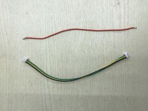
- It's better to cut off the 5V wire of CAN cable, This 5V will cause the target Ubox working, as long as this 5V exist, the target Ubox will keep working. In this article the slave Ubox can be power off is because when button pressed 3 seconds then release, their internal 'EN' signal to the power on circuit is released by their internal receiver, and then the 5V of CAN is lost its support.Can cable with 4 wires:Remove the 5V wire:
- Normally, the two Uboxes will be on/off synchronized, if in some occasion, they are asynchronous, try to press button more than 10 seconds then release button, they may all be off.
- For third party remote and receiver, the theory is same: put control signal to ESCA of master Ubox, let the control signal relay throught CAN bus.
- Remote control signal designate to ESCA is just for simple to understand, actually you can designate it to any one of 4 ESCs you wanted.
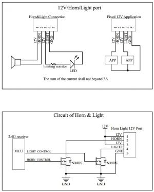
- Since only one Ubox can coupled with Uni1 remote one time, so the horn and light control can only available on one Ubox your Uni1 remote coupled. But you can use the 12 power source of the rest Ubox. Refer this schematic:


Limits and cautions
- Since our solution is based on open source VESC, users should fully understand the risks of open source projects. This article only describes the possibility of this build method, and is not responsible for the damage and accidents caused by users themselves.